-
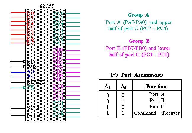
The 82C55 is a popular interfacing component, that can interface any TTL-compatible I/O device to the microprocessor.
-
It is used to interface to the keyboard and a parallel printer port in PCs (usually as part of an integrated chipset).
-
Requires insertion of wait states if used with a microprocessor using higher that an 8 MHz clock.
-
PPI has 24 pins for I/O that are programmable in groups of 12 pins and has three distinct modes of operation.
-
In the PC, an 82C55 or its equivalent is decoded at I/O ports 60H-63H.
-
Mode 0 operation causes the 82C55 to function as a buffered input device or as a latched output device.
-
In previous example, both ports A and B are programmed as (mode 0) simple latched output ports.
-
Port A provides the segment data inputs to display and port B provides a means of selecting one display position at a time.
-
Different values are displayed in each digit via fast time multiplexing.
-
The values for the resistors and the type of transistors used are determined using the current requirements (see text for details).
-
Textbook has the assembly code fragment demonstrating its use.
-
Examples of connecting LCD displays and stepper motors are also given.
-
Port A and/or port B function as latching input devices. External data is stored in the ports until the microprocessor is ready.
-
Port C used for control or handshaking signals (cannot be used for data).
-
Signal definitions for Mode 1 Strobed Input
-
Keyboard encoder debounces the key-switches, and provides a strobe whenever a key is depressed.
-
DAV is activated on a key press strobing the ASCII-coded key code into Port A.
-
Similar to Mode 0 output operation, except that handshaking signals are provided using port C.
-
Signal Definitions for Mode 1 Strobed Output
-
Only allowed with port A. Bi-directional bused data used for interfacing
-
two computers, GPIB interface etc.
-
Timing diagram is a combination of the Mode 1 Strobed Input and Mode 1 Strobed Output Timing diagrams.

