-
DFT started with the insertion of test points into the design.
-
Systematic techniques, such as
scan
,
BIST
and
boundary scan
were developed later.
-
All are approaches to increase
testability
by embedding test structures in the CUT.
-
Testability (one definition by Bennetts '84):
-
"A digital IC is testable if test patterns can be generated, applied, and evaluated in such a way as to satisfy predefined levels of performance (e.g., detection, location, application) within a predefined cost budget and time scale"
-
Cost is key
-- it's the reason why semiconductor manufacturers do not do as much testing as is needed to ensure reliable products.
-
Justification for using DFT today:
-
Test Generation and Application.
-
Deterministic TPG is NP-complete.
-
What is saved in test generation is
offset
in test application time.
-
Random test pattern generation is low cost but yields long test sets and does not guarantee 100% fault coverage.
-
Exhaustive test is not feasible.
-
Characteristics of present VLSI
-
Changes in technology have resulted in:
-
(a) Smaller, faster devices resulting in a faster operational frequency.
-
(b) Higher device density -> more complex designs.
-
(c) Lower power supply voltage -> lower noise immunity.
-
(d) Thinner and longer interconnect -> increase in crosstalk.
-
(e) SOC introduces reuse and new challenges to testing.
-
Characteristics of Present VLSI (cont)
-
Higher density and SOC result in larger designs that make test generation more difficult.
-
Also, accessiblity is more limited, e.g.,
pin-to-gate
ratio is constantly decreasing.
-
An attempt to
quantify
testability by Goldstein '79 and Grason '79 resulted in two testability measures,
controllability
and
observability
.
-
Controllability
reports the cost of placing a specific value on a node.
-
PIs are free (usually assigned a value of 1).
-
Output 1 values for AND gates are more expensive than OR gates.
-
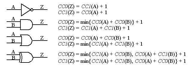
The most popular testability measures are SCOAP;
CC0
/
CC1
(combinational
0
/
1
-controllability and
SC0
/
SC1
(sequential
0
/
1
-controllability)
-
In order to calculate
controllability
, we proceed from
inputs to outputs
.
-
Let's assume the PIs (including branches) are equal to 1.
-
Initially, all TM values are set to
y
.
-
The entries that remain with
y
are either uncontrollable or unobservable at the PO.
-
For nodes
F
,
H
and
G
:
-
CC0
(F) = min{
CC0
(A),
CC0
(B),
CC0
(C)} + 1 = 2
-
CC1
(F) =
CC1
(A) +
CC1
(B) +
CC1
(C) + 1 = 4
-
For nodes
F
,
H
and
G
:
-
CC0
(H) =
CC1
(A) +
CC1
(B) + 1 = 3
-
CC1
(H) = min{
CC0
(A),
CC0
(B)} + 1 = 2
-
CC0
(G) =
CC1
(C) + 1 = 2
-
CC1
(G) =
CC0
(C) + 1 = 2
-
These are then used to compute the PO controllability:
-
CC0
(Y) =
CC0
(F) +
CC0
(H) + 1 = 6
-
CC1
(Y) = min{
CC1
(F),
CC1
(H)} + 1 = 3
-
CC0
(Z) =
CC1
(H) +
CC1
(G) + 1 = 5
-
CC1
(Z) = min{
CC0
(H),
CC0
(G)} + 1 =3
-
Observability
indicates the effort needed to observe the logic value on a node at a PO.
-
Assume the cost of observing a PO is 1.
-
In order to
observe
values, it is necessary to
control
the off path inputs.
-
For example, in order to observe node F on PO Y, it is necessary to control H to 0.
-
CO
Y
(F) =
CO
(Y) +
CC0
(H) + 1 = 5
-
CO
Z
(G) =
CO
(Z) +
CC1
(H) + 1 = 4
-
CO
Y
(H) =
CO
(Y) +
CC0
(F) + 1 = 4
-
CO
Z
(H) =
CO
(Z) +
CC1
(G) + 1 = 4
-
We then proceed to the observability measures for the PIs.
-
Note that they are observable at either
Y
or
Z
.
-
Consider C via Z:
-
CO
Z
(C) =
CO
Z
(G) + 1 = [
CO
(Z) +
CC1
(H) + 1] + 1 = 5
-
Consider C via Y:
-
CO
Y
(C) =
CO
Y
(F) +
CC1
(A) +
CC1
(B) + 1 = [
CO
(Y) +
CC0
(H) + 1]
CC1
(A) +
CC1
(B) + 1 = 8
-
This clearly indicates it is easier to observe
C
through
Z
than
Y
.
-
Note that the observability numbers for
A
and
B
are identical since functions
Y
and
Z
are symmetrical in
A
and
B
.
-
Also, sensitizing
A
and
B
through G
1
yeilds the same observability number as C:
-
CO
YF
(A) =
CO
YF
(B) =
CO
Y
(C) = 8.
-
Note that
SA1
faults on the branches of
A
1
and
B
1
(feeding G
1
) are not detectable because of the redundancy.
-
However, they have
finite
TMs, comparable to other detectable faults.
-
Note that both observability and controllability are important:
-
An easily controllable node is
not necessarily
observable.
-
The ease of observability is
useless
unless we can control the node.
-
Attempts have been made to
combine
these numbers and correlate them with the ease of test pattern generation.
-
This result can then be compared, for example, with the total number of tests that detect each fault (in the exhaustive sense).
-
TMs can be generated quickly (unlike test generation), in
O(n)
time.
-
They are used to aid ATPG algorithms suce as FAN and SOCRATES.
-
They are also used to determine
test insertion points
to facilitate controllability and observability for
built-in self-test
(BIST).
-
Ad hoc strategies (before DFT came along) include:
-
Initializing a sequential circuit before testing it.
-
Adding control and observe points to increase testability.
-
Dividing the circuit into smaller partitions.
-
Although initializing a circuit is not required for proper operation, it is needed in order to test it.
-
However, such sequences may be long and costly to develop.
-
Also, not every sequential circuit has a synchronzing or homing sequence.
-
It is obvious that increasing the number of
observation points
facilitates testing.
-
Add an observation point,
OP
, if node
P
is difficult to observe through
U
.
-
We noted earlier that
A
and
B
have undectable
SA1
faults in this circuit:
-
Leaving these undetected can result in unpredictable behavior.
-
Note that the
controllability
of all node of
U
are affected by the insertion of the control points, as are the
observabilities
of all nodes that go through P.
-
Thus,
CP1
and
CP2
ease control of
P
and affect observability of subcircuit
W
.
-
These add constraints, e.g. to observe,
CP1
and
CP2
must be low.
-
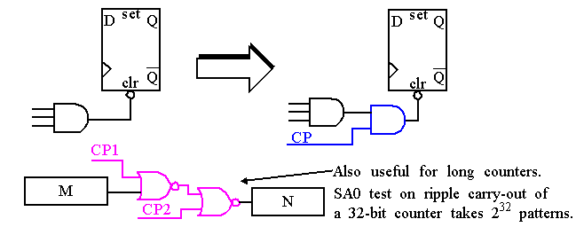
Test point insertion is actually more valuable in
sequential circuits
.
-
It is difficult to reset some storage devices because of complex logic.
-
Here,
M
and
N
can be tested independently.
-
Also, modular counters should be used when possible.
-
For example, replace a
Mod 24
counter with a
Mod 3
and
Mod 8
counter.
-
This reduces the test length from 2
24
to 2
8
.
-
We will soon discuss the
ultimate
for test point insertion for sequential logic (
scan path
).
-
BIST
can make effective use of test point insertion also.
-
Random pattern resistive
(
RPR
) faults are faults not easily detectable by Pseudo-Random (PR) patterns.
-
Control points can be added in troublesome regions, that are treated as PIs by the BIST circuitry.


